Accurately calculating the required heating capacity for a thermal oil heater is a foundational step…
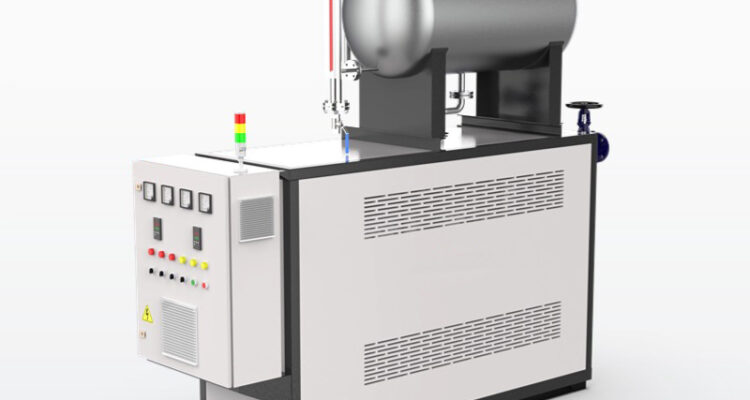
thermal oil heater expansion vessel design
Thermal Oil Heater Expansion Vessel Design: How to Size It Right and Avoid Costly Mistakes
Every thermal oil system needs an expansion vessel. That is not optional. That is not a nice-to-have. It is the single component that keeps your oil from flooding the floor or cavitating your pump when the system heats up. Yet expansion vessel design is one of the most misunderstood parts of thermal oil heater engineering. Operators size them by guesswork. Engineers copy numbers from old projects without checking if conditions have changed. The result is a vessel that is either way too big, wasting money and space, or way too small, which means the relief valve opens every time the system cycles and you are losing oil to atmosphere.
Let us walk through what actually goes into designing an expansion vessel for a thermal oil heater, why most designs get it wrong, and how to get it right the first time.
Why Thermal Oil Systems Need an Expansion Vessel in the First Place
Thermal oil expands when it heats up. A typical synthetic heat transfer fluid expands by roughly 7 to 10 percent of its total volume between ambient temperature and maximum operating temperature. Mineral-based oils expand even more, sometimes up to 12 percent. That expansion has to go somewhere.
Without an expansion vessel, the oil has nowhere to go. Pressure builds rapidly. The relief valve opens. Oil sprays out. You lose fluid, you lose money, and you create a fire hazard around the heater. The expansion vessel absorbs that extra volume, keeps the system pressure stable, and gives the pump a steady supply of oil at the inlet.
But here is the part people miss. The expansion vessel does not just sit there passively. It has to be sized for the exact volume of oil in the system, the exact temperature range, and the exact operating pressure. Change any one of those variables and the vessel that worked perfectly last year is now either oversized or dangerously undersized.
Open Tank vs Closed Vessel: Which Design Fits Your System
The Open Expansion Tank
An open tank is literally a tank with a pipe going up to atmosphere. The oil expands into the tank, and any excess overflows through a vent pipe. This is the simplest design in existence. It works. It is cheap. It requires no maintenance. But it has serious drawbacks that make it unsuitable for most modern thermal oil systems.
First, the oil is in direct contact with air. Oxidation accelerates dramatically. The oil degrades faster, forms sludge, and needs replacement more often. Second, the system has to be installed above the highest point in the loop, which means a tall open tank sitting on a platform or roof. That is a structural and safety nightmare. Third, moisture from the air dissolves into the oil over time, and water in thermal oil is a recipe for vapor lock and pump cavitation.
Open tanks still show up in small, low-temperature systems where the operator does not care about oil life and the installation height is not an issue. For anything running above 200 degrees Celsius or serving a critical process, an open tank is a liability.
The Closed Pressurized Expansion Vessel
A closed vessel is a sealed steel tank with a gas cushion, usually nitrogen, on top of the oil. As the oil expands, it compresses the gas cushion. As the oil cools and contracts, the gas pushes the oil back into the system. No air contact. No oxidation. No moisture pickup. The system can be installed anywhere, and the vessel can be mounted at any height.
There are two types of closed vessels: bladder type and diaphragm type. A bladder vessel has a rubber bladder that separates the gas from the oil. The bladder is pre-charged with nitrogen at a set pressure. When oil enters the vessel, it pushes against the bladder and compresses the gas. When oil leaves, the gas expands and pushes the oil back out.
A diaphragm vessel uses a flexible steel diaphragm instead of a rubber bladder. The diaphragm is more durable at high temperatures and does not degrade as fast as rubber. For thermal oil systems running above 250 degrees Celsius, a diaphragm vessel is the better choice because rubber bladders start to harden and crack at those temperatures.
How to Calculate the Right Expansion Vessel Size
The Basic Sizing Formula
The expansion vessel volume is not a guess. It comes from a calculation based on three numbers: the total oil volume in the system, the expansion coefficient of the oil, and the pressure ratio between the pre-charge pressure and the maximum operating pressure.
The formula looks like this. The required gas volume equals the total oil volume multiplied by the expansion coefficient, divided by one minus the ratio of pre-charge pressure to maximum operating pressure. That last part is the one most people mess up.
The pre-charge pressure must be set correctly. If the pre-charge is too high, the gas cushion cannot compress enough to absorb the oil expansion, and the relief valve opens. If the pre-charge is too low, the gas cushion takes up too much of the vessel volume, and there is not enough room for the expanded oil. The sweet spot is usually 0.3 to 0.5 bar below the pump suction pressure at ambient temperature.
Accounting for System Volume Accurately
The total oil volume includes everything: the heater coils, the process equipment, all the piping, the pump, and the vessel itself. Most operators forget to include the piping volume, which can be significant in large systems with long pipe runs. A 100-meter run of 50mm pipe holds roughly 20 liters of oil. Multiply that by dozens of pipe runs and you are talking about hundreds of liters that were not in the original calculation.
Also account for the oil that stays in the vessel at maximum temperature. The vessel is not empty when the system is hot. It still contains a cushion of gas and a residual volume of oil. That residual oil volume reduces the effective expansion capacity of the vessel, so the vessel must be sized larger to compensate.
Common Design Mistakes That Cause Real Problems
Undersizing the Vessel to Save Money
This is the most frequent error. An engineer calculates the minimum required volume and then picks a vessel that is exactly that size, leaving zero margin. In practice, the system oil volume changes over time. Pipes get cleaned and re-welded, adding volume. New process equipment gets added. The oil itself degrades and its expansion coefficient shifts slightly. A vessel with no margin will start triggering the relief valve within months of installation.
The rule of thumb is to add at least 20 to 25 percent to the calculated volume. That extra capacity absorbs the inevitable changes in system volume and gives you breathing room during transient conditions like emergency shutdowns or rapid cool-downs.
Wrong Pre-Charge Pressure
Setting the pre-charge pressure wrong is like building a house on the wrong foundation. The vessel will technically work, but it will work poorly. The gas cushion will either be too stiff to absorb expansion or too soft to push oil back into the system during cool-down.
Always set the pre-charge with the system cold and empty of oil. Use a calibrated nitrogen regulator and a pressure gauge on the gas side of the vessel. Do not estimate. Do not use shop air. Nitrogen is dry and inert. Shop air contains moisture and oxygen, both of which accelerate oil degradation inside the vessel.
Ignoring the Maximum Allowable Temperature
Every expansion vessel has a maximum temperature rating. Bladder vessels are typically rated to around 100 to 120 degrees Celsius on the oil side. Diaphragm vessels can handle 200 to 250 degrees Celsius or more. If your thermal oil system operates at 300 degrees Celsius and you install a standard bladder vessel, the rubber will degrade within weeks. The bladder will crack, the gas will mix with the oil, and the vessel will stop functioning entirely.
Match the vessel type to the oil temperature. If the operating temperature exceeds the bladder rating, use a diaphragm vessel or install a cooling coil on the vessel inlet to keep the oil temperature below the bladder limit.
Installation Details That Make or Break the Design
Vessel Placement Relative to the Pump
The expansion vessel must be installed on the suction side of the circulation pump, as close to the pump inlet as possible. This ensures the pump always sees a positive inlet pressure and never cavitates. If the vessel is placed on the discharge side or too far from the pump, the pressure drop in the piping can cause the pump to lose its prime, especially during cold starts when the oil is thick and the pump is struggling.
The connection pipe between the vessel and the system should be as short and as wide as practical. A long, narrow connection creates pressure drop and slows down the response of the gas cushion. When the oil expands rapidly during a heat-up cycle, the vessel needs to accept that oil quickly. A restricted connection delays that acceptance and causes a pressure spike that can trigger the relief valve.
Piping the Relief Line Correctly
The expansion vessel relief line must go to a safe location, not just vented to atmosphere. If the relief valve opens, it means oil is being expelled from the system. That oil is hot, it is under pressure, and it will spray. Route the relief line to a drain tank or a cool-down vessel where the oil can be collected and returned to the system. Do not let it drip onto the floor or into a sewer.
Also install a isolation valve on the relief line so you can test the valve without shutting down the entire system. Test it at least once per year. A relief valve that has not been tested in two years is not a safety device. It is a decoration.
Monitoring the Vessel Over Time
A properly designed expansion vessel needs periodic checks. Monitor the gas pre-charge pressure every three to six months. If the pressure has dropped, the bladder or diaphragm has leaked and the vessel needs servicing. Check the oil level inside the vessel during maintenance shutdowns. If oil is filling more of the vessel than it should, the gas cushion has lost volume and the vessel is losing its effectiveness.
Keep a record of every relief valve activation. Even a single activation means the vessel was undersized, the pre-charge was wrong, or something else in the system has changed. Do not ignore it. Investigate it. The data from those records will tell you when the vessel needs to be resized or replaced before it becomes an emergency.
Related Posts