Accurately calculating the required heating capacity for a thermal oil heater is a foundational step…
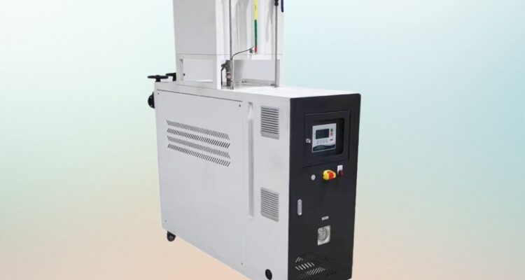
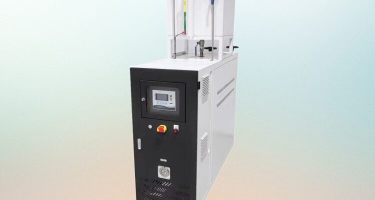
thermal oil heater compact structure
Compact Thermal Oil Heater Structure: How Small Footprints Deliver Big Performance
Space is expensive. Whether you are retrofitting a heater into an existing plant room, fitting a system onto a crowded rooftop, or designing a skid that needs to ship on a single truck, the physical size of your thermal oil heater matters a lot. Compact structure design is not about cramming components together. It is about rethinking every element — the heater core, the burner, the piping, the controls — so they occupy less space without sacrificing performance or safety. Getting it wrong means vibration, poor maintenance access, and a system that never runs right. Getting it right means a heater that fits where you need it and does its job for years.
Why Compact Design Is Harder Than It Looks
Most people assume compact means smaller version of the same thing. That is not how thermal oil heaters work. Shrinking the footprint changes the thermal dynamics, the structural loads, the maintenance access, and the safety margins. A heater that fits in a tight space but cannot be serviced is not compact — it is a liability.
The core challenge is heat transfer density. You need a certain amount of heating surface to deliver the required thermal output. In a conventional heater, that surface is spread across a large bank of tubes. In a compact heater, you have to pack more surface into less volume. This means higher heat flux on the tube walls, which means more careful attention to oil film temperature, flow velocity, and tube metal temperature. Push too hard and the oil cracks locally, forms coke, and fouls the tubes faster than a larger heater would.
Weight is another issue. A compact heater concentrates mass into a smaller area. The skid or foundation must handle that concentrated load. If the frame is not designed for it, you get deflection, misalignment, and stress on the pipe connections. Compact does not mean light. It means dense.
Core Design Strategies for a Smaller Footprint
Vertical Tube Arrangement
The most common way to shrink a thermal oil heater is to go vertical instead of horizontal. A horizontal heater spreads tubes across a wide firebox. A vertical heater stacks tubes on top of each other inside a tall, narrow chamber. The footprint drops dramatically — sometimes by 40% to 60% — while the heating surface stays the same.
Vertical tube heaters use a natural circulation pattern inside the tubes. Hot oil rises, cooler oil falls. This reduces the need for high-velocity forced circulation in some designs, which simplifies the piping and allows smaller pumps. The trade-off is that vertical heaters are taller, which creates headroom requirements in the installation space. You save floor space but need ceiling clearance.
The burner in a vertical heater sits at the bottom of the firebox. The flame travels upward through the tube bank. This gives a more even heat distribution across the tubes compared to a horizontal design where the flame tends to concentrate at one end. More even heat means fewer hot spots and longer tube life, which is a real advantage in a compact system where there is less margin for error.
Coiled Tube Configuration
Instead of straight tubes running the length of the heater, some compact designs use coiled tubes. The oil flows through a spiral or helical coil inside the firebox. This packs more heating surface into a smaller volume because the coil folds back on itself.
Coiled tube heaters are common in electric thermal oil heaters where the heating element sits inside the coil. They are also used in some fired designs where space is extremely limited. The downside is higher pressure drop. Oil flowing through a tight coil fights friction, which means the pump has to work harder. For systems above 500 kW, the pressure drop can become a limiting factor. For smaller systems, it is manageable.
Cleaning coiled tubes is harder than cleaning straight tubes. A mechanical brush or high-pressure jet does not navigate a coil as easily as it runs through a straight pipe. If you use coiled tubes, plan for more frequent chemical cleaning or design the coil so it can be pulled out and cleaned offline.
Integrated Burner and Firebox Design
In a conventional heater, the burner is a separate component bolted to the front of the firebox. In a compact design, the burner is often integrated into the firebox structure itself. The burner nozzle sits flush with the firebox wall, and the combustion chamber is shaped to direct the flame tightly around the tube bundle.
This integration saves space because you eliminate the gap between the burner and the firebox. It also improves combustion efficiency because the flame is contained and directed rather than spreading out into a larger chamber. The firebox walls stay hotter, which improves heat transfer to the tubes.
The catch is maintenance access. An integrated burner is harder to remove and service than a bolt-on burner. If the burner needs nozzle replacement or tuning, you have to work in a tighter space. Design the firebox with removable panels so you can reach the burner without dismantling the entire heater.
Piping and Component Integration
Minimizing Pipe Runs
In a compact system, every centimeter of pipe counts. Long pipe runs between the heater, pump, and expansion tank add bulk, pressure drop, and thermal loss. The solution is to place components as close together as possible.
The circulating pump should sit directly next to the heater outlet. The suction line should be under 1 meter if possible. The discharge line runs straight to the process connection. No loops, no unnecessary elbows, no detour valves. Every fitting you add is a potential leak point and a maintenance item.
The expansion tank should mount on top of the heater or on a short riser immediately adjacent. Do not run a long pipe to a remote tank. The tank needs to be at the highest point, and in a compact skid, that usually means on top of the heater. A tall, narrow tank fits better than a wide, short one.
Valve and Instrument Consolidation
A compact heater does not have room for a sprawling valve manifold. Consolidate valves into a compact block or use multiport valves that combine isolation, bypass, and drain functions into a single body. This reduces the number of flanges, the number of potential leak points, and the physical space taken up by the valve assembly.
Instrumentation should be minimal but strategic. You need oil temperature at the inlet and outlet, oil pressure at the pump discharge, and flue gas temperature for fired systems. That is it. Do not add gauges and sensors for the sake of redundancy. Every instrument adds a penetration in the skid frame, a wiring run, and a calibration schedule. Keep it lean.
Control Panel Placement
The control panel on a compact skid often mounts directly on the frame or on a bracket attached to the heater. It does not get its own separate cabinet. This saves space but means the panel is exposed to heat and vibration. Use a NEMA 4X rated enclosure if the panel sits outdoors, and mount it on vibration isolators if it sits on the skid frame.
Keep the panel wiring short. Long cable runs from the panel to the burner, pump, and sensors add noise and failure points. Route all cables through a single conduit bundle along the skid frame. Label everything clearly. In a compact system, there is no room for confusion.
Structural Considerations in Compact Heaters
Frame and Support Design
A compact heater concentrates weight into a small area. The skid frame must be stiff enough to resist deflection under that load. Use a box section or I-beam frame with cross bracing. A simple flat plate frame will flex under the weight of a vertical heater, and that flex misaligns the pipe connections.
Vibration isolation is critical. The circulating pump generates vibration that travels through the pipe and into the frame. Without isolators, that vibration loosens bolts, cracks welds, and fatigues the pipe supports. Use spring isolators or rubber mounts rated for the pump weight and operating temperature. Place them under the pump feet, not under the heater. The heater is rigid by design. The pump is the vibration source.
Thermal Expansion in Tight Spaces
Thermal expansion is not less of a problem in a compact heater — it is worse. The pipes are shorter, which means each millimeter of growth represents a larger percentage of the total run. A 2-meter pipe that grows 3mm at 300°C has a strain of 0.15%. That sounds small, but it is enough to crack a flange gasket or buckle a support.
Use expansion loops or bellows on every pipe run, even the short ones. A simple U-bend in the pipe gives enough flexibility to absorb growth. Do not rely on the pipe supports to flex — they are not designed for it.
Sliding supports are essential in a compact system. Fixed supports hold the pipe in place at anchor points. Sliding supports let the pipe move freely between anchors. In a tight skid, you may only have room for one or two anchors. Everything else must slide.
Heat Transfer Density and Its Limits
Packing more heating surface into less space increases the heat flux — the amount of heat per unit area of tube surface. Higher heat flux means the oil film on the inside of the tube must stay above its cracking temperature. If the oil velocity drops or the flow becomes uneven, the film temperature spikes locally, the oil cracks, and coke forms on the tube wall.
This is the main risk of compact design. You are pushing the oil harder in a smaller space. To manage this, keep the oil velocity high — at least 1 m/s inside the tubes. Use a pump sized for the flow rate, not just the pressure. Monitor the pressure drop across the heater regularly. A rising pressure drop means tubes are fouling, and in a compact system, fouling happens faster because there is less surface area to absorb the deposits.
Do not exceed the manufacturer’s rated heat flux for the tube material. Carbon steel tubes have a maximum heat flux limit that depends on the oil temperature and flow rate. Go beyond that limit and tube failure is not a matter of if — it is a matter of when.
When Compact Structure Makes Sense
Compact thermal oil heaters work best when space is the primary constraint. Rooftop installations, retrofit projects, mobile skids, and offshore platforms all benefit from a smaller footprint. They also work well for smaller heating loads — under 1 MW — where the physical size of a conventional heater would be disproportionate to the output.
They make less sense when maintenance access is a priority. A compact heater with no room to reach the burner, no space to pull a tube, and no clearance to service the pump is a compact heater that will cost you in downtime. Always leave enough access for the tasks that will actually happen — tube inspection, nozzle replacement, pump seal change, oil sampling.
Compact design also makes less sense for very high temperature applications above 380°C. The heat flux limits become tighter, the material requirements go up, and the safety margins shrink. At those temperatures, a larger heater with lower heat flux is safer and more reliable.
The Trade-Offs You Need to Accept
Going compact means accepting certain compromises. You lose some maintenance access. You gain higher heat flux, which demands better oil management. You save floor space but may need more headroom. You simplify installation but complicate servicing.
None of these trade-offs are dealbreakers if you plan for them at the design stage. The problem is when someone specifies a compact heater for space reasons and then acts surprised when the tubes foul faster or the burner is hard to reach. The compact structure is not a shortcut. It is a different engineering problem with different constraints. Solve it with the right tube layout, the right burner integration, the right piping geometry, and the right maintenance plan, and you get a heater that fits where it needs to fit and performs where it needs to perform.
Related Posts