Accurately calculating the required heating capacity for a thermal oil heater is a foundational step…
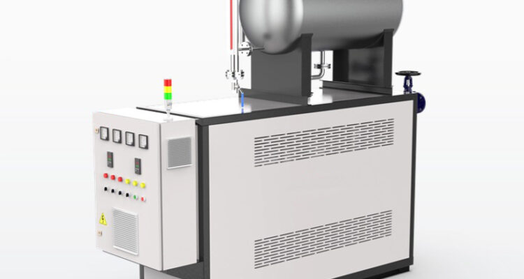
thermal oil heater expansion tank sizing
When you are setting up or upgrading a thermal oil heater system, getting the expansion tank sizing right is one of the most overlooked but high-impact steps to avoid operational headaches down the line. A tank that is too small will spill over hot fluid when the system heats up, create unexpected pressure spikes, and trigger unnecessary safety shutdowns. A tank that is far larger than needed wastes valuable floor space, slows down heat-up times, and increases the risk of fluid oxidation from extra air contact inside the tank. Proper sizing does not follow a one-size-fits-all rule, and it has to account for your specific system’s operating conditions, heat transfer fluid traits, and long-term usage plans.
Core Volume Calculation Based on Thermal Expansion of Heat Transfer Fluid
The starting point for any accurate expansion tank sizing is calculating the exact volume difference between cold fluid at ambient startup temperature and fully heated fluid at the system’s maximum operating temperature. Every heat transfer fluid has a unique volumetric expansion coefficient, and this value changes noticeably across different temperature ranges, so you cannot use a generic number pulled from unrelated system guides.
You first take the total volume of fluid held in every part of your full loop, including the thermal oil heater internals, all connected piping, heat exchangers, and process equipment, then multiply that total system volume by the fluid’s verified expansion factor for your specific temperature rise. After you get the total expanded volume that will push out of the main loop when the system hits peak heat, you set the sizing parameters so that the tank sits at roughly 25% full when the entire system is cold and idle, and never goes above 75% full when the system is running at its absolute maximum design temperature. This 25% to 75% operating window leaves plenty of empty space to absorb unexpected volume surges from temporary temperature spikes, and it also maintains enough minimum fluid head to keep the circulation pump primed and running smoothly even during the coldest startup conditions.
Safety Factor for Long-Term System Flexibility
A well-sized expansion tank never stops at just the basic thermal expansion calculation, because real-world industrial systems change over their multi-decade service life. Many facilities switch to a different heat transfer fluid years after the initial installation, and the new fluid often has a higher volumetric expansion coefficient than the original one the system was designed for. If you did not build in extra buffer space during sizing, this simple fluid swap can push the tank past its safe maximum fill level and create dangerous overflow risks.
You also need to account for the small amount of extra volume that gets released when old, partially degraded fluid breaks down and generates light volatile components during regular operation. These low-boiling fractions take up extra space in the upper section of the tank, and if you did not leave enough empty headroom, they can create unexpected pressure buildup that trips your safety relief valve. For systems that run 24/7 for months at a time without full shutdowns, adding this reasonable extra safety margin also eliminates the need to resize the tank if you later extend the piping loop or add new process heat exchangers that increase the total system fluid volume. This small upfront consideration saves you from costly, time-consuming tank replacement work years down the line.
Sizing Adjustments Tied to Tank Location and System Pressure
Where you mount the expansion tank in relation to the thermal oil heater and circulation pump has a direct impact on how large it needs to be to work as intended. The standard recommended placement is on the suction side of the main circulation pump, at the highest point of the entire system, and positioned at least 1.5 meters above the pump centerline. This layout ensures the tank can maintain consistent positive pressure on the pump inlet, eliminating cavitation risk, and it also lets the tank collect all expanded fluid naturally without needing extra forced flow paths.
If you have to place the tank closer to the heater outlet or at a lower elevation than the highest point of the loop, you will need to add extra volume to your final sizing calculation to compensate for the pressure differences across the system. For systems that use inert gas blanketing on the top of the expansion tank to prevent fluid oxidation, the tank’s internal pressure rating and the compressibility of the gas cushion also factor into sizing. The gas space at the top of the tank has to be large enough to absorb the full expanded fluid volume without pushing the system pressure past the maximum allowable working pressure of any component in the loop. Even small miscalculations here can lead to inconsistent pressure swings that disrupt temperature control, damage pump seals, or trigger unnecessary safety trips during normal operation.
Related Posts