Asphalt plant operations rely on consistent, reliable high-temperature heat to keep aggregate drying, bitumen storage,…
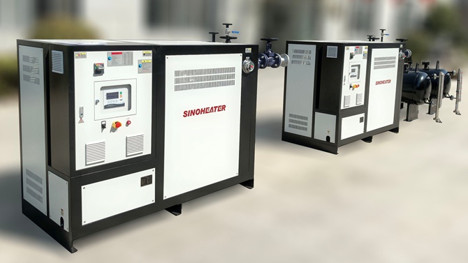
thermal oil heater combustion air system
A properly functioning combustion air system forms the backbone of reliable, efficient operation for any thermal oil heater setup. It delivers the exact volume of clean, temperature-stabilized air needed to support complete, consistent fuel combustion, and it directly shapes everything from overall heat transfer efficiency to long-term operational stability across the entire system. Even small, unaddressed issues in this part of the heater can create uneven flame patterns, wasted fuel, unnecessary thermal stress on internal components, and unexpected drops in the consistent heat output the whole process relies on.
Core functional roles of a well-designed combustion air system
Every component in this system works together to solve the most common pain points that reduce thermal oil heater performance over time. It does not simply push air into the combustion chamber, it conditions that air, meters it precisely, and directs it in a pattern that supports even, stable flame formation across all operating load ranges.
Stable combustion support across variable loads
The system adjusts airflow volume dynamically to match real-time fuel feed rates, so the air-fuel ratio stays balanced even when the heater ramps up to full output or drops down to low standby levels. This prevents incomplete combustion that leaves unburned residue on heat exchange surfaces, which would otherwise build up over time and create an insulating layer that cuts down heat transfer efficiency. A well-calibrated air supply also eliminates sudden flameouts or unstable flame surges that can trigger unnecessary safety shutdowns and disrupt continuous process operation.
Thermal efficiency and equipment protection
By preheating incoming ambient air using waste heat recovered from flue gas, the system raises the temperature of combustion air before it enters the chamber, reducing the amount of fuel needed to reach and maintain the target combustion temperature. This small adjustment creates noticeable improvements in overall system efficiency over long running cycles. It also prevents cold ambient air from hitting the high-temperature combustion chamber walls directly, which avoids uneven thermal expansion, localized material stress, and premature wear on the chamber structure.
Key layout and component design considerations
Every part of the air system layout is built to support consistent performance, easy maintenance access, and reliable long-term operation without unexpected failures.
Air intake and filtration setup
The air intake point is positioned in a location that draws in clean, uncontaminated ambient air, away from exhaust vents, dusty process zones, or areas that pull in fumes with high moisture or particulate content. Multi-stage filtration removes fine dust, floating debris, and other contaminants before the air moves further into the system, preventing these particles from scratching blower blades, clogging small airflow ports, or building up inside the combustion chamber to disrupt stable flame patterns. Many installations route the main intake duct to draw air directly from outside the facility, which delivers a steady, consistent air supply that is not affected by changing indoor air pressure or variable workplace conditions.
Blower and airflow regulation assembly
The blower unit is sized to deliver enough static pressure to push the full required airflow through every part of the ducting, even when filters start to build up minor levels of normal dust loading over time. The regulation system uses smooth, variable speed adjustment rather than simple on-off switching, so operators can fine-tune airflow volume in small, precise increments to match exact fuel input and current heater load. This level of precise control eliminates the sharp, sudden airflow changes that can make flame patterns unstable and create uneven heat distribution inside the heat exchanger.
Ducting and distribution to the combustion chamber
Air ducts are designed with smooth, gradual bends and minimal unnecessary restrictions to cut down on excess airflow resistance and pressure loss across the whole system. The final air distribution assembly at the chamber inlet splits and directs the incoming air into multiple controlled streams, creating the exact turbulent mixing pattern needed to make sure every part of the fuel stream comes into full contact with oxygen. This complete mixing eliminates dead zones inside the chamber where incomplete combustion would otherwise occur, and it spreads the flame evenly across the full combustion area instead of letting it concentrate on a single small section of the chamber wall.
Routine maintenance and performance optimization practices
Regular, small scheduled checks and adjustments keep the combustion air system running at peak performance far longer, and prevent minor unaddressed issues from growing into costly, unplanned downtime events. Operators inspect filter condition at consistent intervals, replacing or cleaning elements before excessive dust buildup creates a noticeable pressure drop across the system that starves the chamber of required air. They also check blower blade condition, duct seal integrity, and damper movement on a regular schedule, tightening loose connections and removing minor dust buildup that can throw off carefully calibrated airflow balance.
Periodic air-fuel ratio calibration runs, done under different operating load conditions, make small adjustments to airflow settings to compensate for minor wear on system components or seasonal changes in ambient air temperature and density. These regular fine-tuning steps keep combustion complete and stable, maintain consistent heat transfer performance across the thermal oil heater, and extend the service life of every major component in the full system.
Related Posts