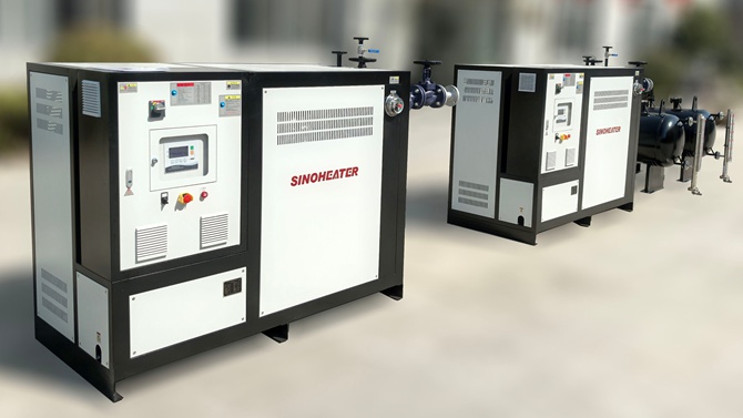
Asphalt plant operations rely on consistent, reliable high-temperature heat to keep aggregate drying, bitumen storage,…
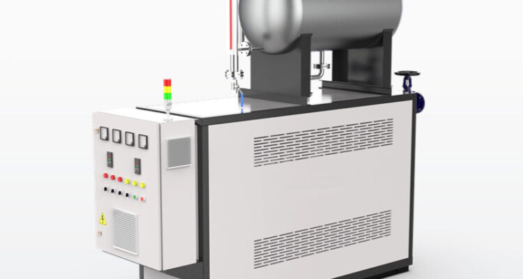
thermal oil heater thermal fluid circulation system
A well-designed thermal fluid circulation system forms the core of every reliable thermal oil heater installation, moving heat transfer medium in a continuous closed loop to carry thermal energy from the heat source to every point of process demand. Unlike open heating circuits that lose medium through evaporation or venting, this fully closed architecture minimizes fluid loss, reduces contamination risk, and maintains highly consistent heat delivery across months of non-stop industrial operation. Every component in the circulation loop works in coordination to preserve flow stability, prevent thermal degradation, and support long-term system performance at elevated operating temperatures.
Core Circulation Loop Layout and Flow Path Design
The primary circulation pump is positioned at the coolest section of the circuit, directly downstream from the process return line, to ensure the thermal oil entering the pump inlet stays well below its vaporization temperature. This arrangement eliminates cavitation risk even when the system runs at maximum operating temperature, as the positive static pressure maintained by the expansion tank pushes a steady, fully liquid stream into the pump impeller. No vapor bubbles form at this point, so flow remains smooth and consistent across the full range of system load conditions.
The flow path is arranged to maintain continuous, positive flow through every section of the heater heating coil. There are no low-flow dead zones where thermal oil could become trapped and stagnant, which would lead to localized overheating, thermal cracking, and carbon deposit formation on internal metal surfaces. Even at reduced load levels, the minimum circulation velocity is carefully maintained to ensure every portion of the heat transfer medium moves at a speed that prevents sediment buildup and supports uniform heat absorption.
All process heat consumers are connected in a parallel or properly balanced series arrangement that avoids uneven flow distribution. Each branch receives the correct volume of circulating thermal oil to meet its specific heat demand, so no single connected unit is starved of flow while other sections receive more than required. This balanced layout eliminates the common problem of uneven process temperatures across different production zones that plagues poorly designed circulation systems.
Temperature and Pressure Stability Control Logic
Supply and return temperature sensors are installed at key points across the loop to track thermal performance in real time, rather than only monitoring the heater outlet alone. This allows operators to detect unexpected temperature differences that indicate fouling buildup on heat transfer surfaces, flow blockages, or abnormal heat demand changes that would otherwise go unnoticed until they create larger operational issues. These readings feed directly into the main control logic to adjust heat generation output and keep supply temperature stable within a very narrow band.
Differential pressure monitoring across the circulation pump and full heater section provides immediate warning of changing system resistance. A gradual rise in pressure differential over time is one of the earliest reliable signs of internal fouling or fluid degradation, appearing long before any noticeable drop in heat delivery performance. This early alert gives maintenance teams time to schedule targeted cleaning or fluid treatment during planned production breaks, instead of facing unexpected sudden flow loss during critical operation periods.
A properly sized pressure relief valve installed on the low-pressure return side provides passive overpressure protection for the entire circulation loop. This safety component is set to trigger well below the maximum pressure rating of any piping or heater component, safely diverting excess fluid back to the expansion tank if unexpected thermal expansion creates abnormal pressure spikes. This simple, reliable protection prevents catastrophic component failure even under unusual operating fault conditions.
Long-Term Circulation System Health Management
Even during full system shutdown periods, maintaining slow, low-speed circulation for several hours after the heat source is turned off prevents uneven cooling that could create thermal stress in heater coils and piping. This extended post-run circulation also flushes residual heat away from the hottest sections of the heater, preventing trapped thermal oil from being held at extreme temperature with no flow, which would otherwise accelerate fluid degradation and carbon deposit formation.
Regular inline filter inspection and element replacement removes fine carbon particles and oxidation byproducts that naturally accumulate in the thermal fluid over time. These small suspended particles act as abrasives that can damage pump seals, and they also settle on heat transfer surfaces to form insulating fouling layers that reduce system efficiency. Consistent filtration keeps the fluid clean and preserves the original heat transfer performance of the entire loop for much longer.
Periodic full system venting removes dissolved air and non-condensable gases that slowly build up inside the circulation loop over months of operation. These gas pockets can get trapped at high points in the piping, blocking flow, creating local corrosion, and disrupting the smooth operation of pressure and temperature sensors. Clearing these gases on a scheduled basis maintains full flow path integrity and prevents hidden performance drift that would slowly reduce the reliability of the entire thermal fluid circulation system.
Related Posts