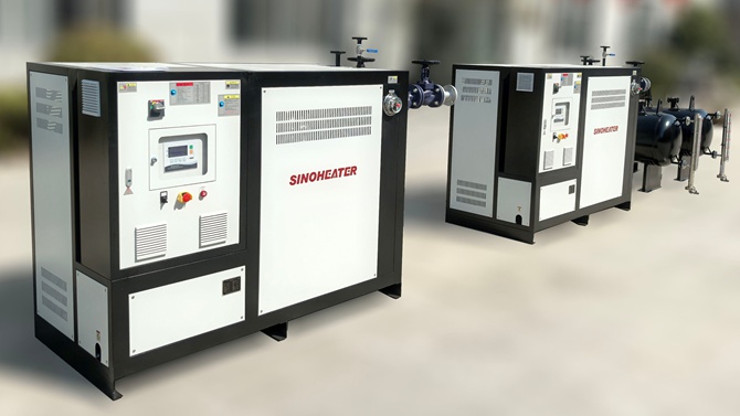
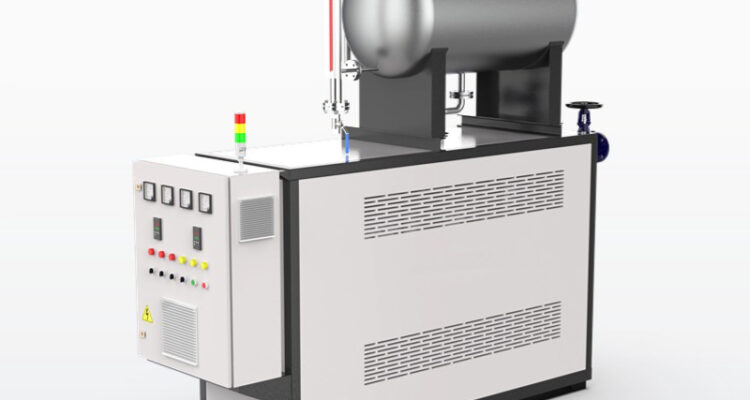
Asphalt plant operations rely on consistent, reliable high-temperature heat to keep aggregate drying, bitumen storage,…
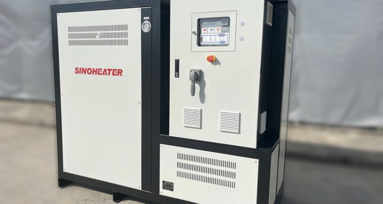
thermal oil heater circulation system design
A well-engineered thermal oil heater circulation system forms the backbone of consistent, reliable high-temperature process heating across a wide range of industrial operations. The design of this system directly impacts long-term thermal efficiency, operational stability, and the overall service life of both the heat transfer fluid and connected process equipment. A carefully structured layout avoids common pitfalls like uneven flow distribution, localized overheating, and unexpected thermal lag that can disrupt continuous production workflows.
Primary Circuit Layout and Flow Path Optimization
The core circulation circuit is designed to maintain fully turbulent flow across every segment of the main piping network, ensuring the thermal oil never settles into stagnant low-velocity zones that encourage coking and material degradation. The flow path is arranged to minimize unnecessary bends, abrupt diameter changes, and dead legs that create flow resistance and waste pump power, while keeping the total straight pipe length between the heater outlet and first process load as balanced as possible. This layout ensures every connected heat consumer receives a consistent, uniform supply temperature without noticeable fluctuations, even when multiple process loads are switched on or off at different stages of the production cycle. All pipe routing also accounts for natural thermal expansion of hot oil lines, with properly positioned expansion loops that eliminate mechanical stress that could cause pipe deformation or joint leakage over time.
Pump Selection and Installation Positioning
The circulation pump is placed in the cool inlet line of the thermal oil heater, rather than the high-temperature outlet side, to ensure the fluid entering the pump impeller is kept at the lowest possible system temperature. This arrangement prevents vapor bubble formation inside the pump casing, which eliminates cavitation risk that can damage pump components and create disruptive flow pulsations. The pump is sized to deliver a consistent flow rate that maintains the minimum required turbulent flow threshold across the entire circuit, even when minor fouling builds up on heat exchanger surfaces after months of operation. A dedicated bypass loop around the pump body also guarantees a minimum continuous flow through the heater, even if all downstream process loads are temporarily closed off, protecting the heater core from dangerous overheating.
Expansion and Deaeration Architecture
The expansion tank is positioned at the highest point of the entire circulation system, at a safe vertical elevation above all other system components, to maintain consistent positive pressure at the pump inlet across all operating conditions. This tank acts as the core buffer that accommodates the significant volumetric expansion of thermal oil as it heats up from ambient temperature to full operating temperature, preventing dangerous pressure spikes that could trigger safety relief events. The system also includes a dedicated deaeration assembly that continuously vents dissolved air and light volatile compounds out of the circulating fluid, eliminating the risk of gas pockets that can cause flow interruptions, noisy pump operation, and uneven heat transfer across the heater core. All vent lines routed from the high points of the piping network back to the expansion tank are sloped at a consistent downward angle to prevent trapped fluid from blocking air flow and disrupting proper venting.
Filtration and Side Loop Maintenance Design
A full-flow strainer is installed immediately at the pump suction port to catch any loose metal shavings, residual welding slag, or carbon particle debris that could circulate through the system and scratch pump seals or damage precision process heat exchanger surfaces. A separate small, continuously running filtration side loop is also routed off the main return line, pulling a small fraction of the circulating oil through a fine filter assembly at a steady, controlled rate. This side loop gradually removes fine suspended carbon particles from the fluid over time, slowing down the fouling rate on heat transfer surfaces and extending the usable service life of the thermal oil. This arrangement allows filter element replacement to be performed without shutting down the main system, supporting continuous operation even during routine maintenance activities.
Temperature Control and Safety Interlock Integration
The system’s temperature sensing points are strategically placed at critical locations including the heater outlet, the main supply manifold, and the return line right before the circulation pump, to capture a complete, accurate picture of thermal conditions across the full circuit. The control logic modulates heater firing rate in direct response to real supply temperature readings, avoiding frequent on-off cycling that causes unnecessary thermal stress on both the heater and connected process equipment. All safety interlocks are hardwired to trigger immediate protective action if flow rate drops below the minimum safe threshold, if outlet temperature exceeds pre-set limits, or if system pressure moves outside the defined operating band. This layered safety architecture prevents the vast majority of preventable system faults that could lead to thermal oil degradation, component damage, or unplanned production shutdowns.
Related Posts