Asphalt plant operations rely on consistent, reliable high-temperature heat to keep aggregate drying, bitumen storage,…
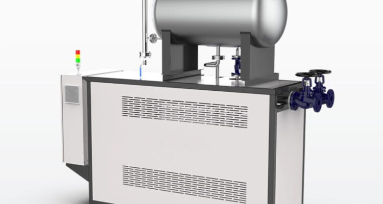
thermal oil heater combustion chamber inspection
Routine combustion chamber inspection is one of the most critical, yet often overlooked, parts of thermal oil heater preventive maintenance. Over months of continuous operation, small issues like soot buildup, refractory wear, and misaligned burner components can slowly degrade combustion efficiency, create unplanned safety risks, and even lead to unexpected unplanned shutdowns. A structured, step-by-step inspection process catches these issues long before they escalate, keeping the heater running reliably and reducing unnecessary fuel waste across every operating cycle.
Pre-inspection system lockout and preparation
Before any physical inspection work begins, full system isolation is non-negotiable to eliminate all risk of accidental ignition, unexpected pressure release, or contact with hot residual surfaces. Skipping these preliminary steps creates avoidable hazards for maintenance staff, and can also damage system components if the chamber is opened before it has fully stabilized. Taking time to complete this preparation thoroughly also ensures you can carry out the full inspection without rushing or cutting corners.
Full energy source isolation
Lock out and tag all fuel supply lines, electrical power feeds to the burner assembly, and system circulation pumps to make absolutely no power or fuel can reach the combustion chamber while work is underway. Close and secure all manual isolation valves on both the fuel inlet and flue gas outlet sides, and confirm no residual pressure remains trapped in the fuel line before you proceed. This step eliminates every possible source of unintended activation that could create danger once the chamber access panel is opened.
Controlled chamber cooling and ventilation
Even after the heater is fully shut down, the combustion chamber walls and internal components can hold extreme residual heat for many hours. Allow the system to cool down gradually to a temperature low enough for safe human entry, and run forced fresh air ventilation through the chamber for a full period of time to flush out all accumulated flue gas, unburned fuel vapor, and stagnant low-oxygen air. Test the internal atmosphere to confirm no hazardous fumes remain and oxygen levels are stable before any staff member opens the access panel.
Internal component condition assessment
Once the chamber is safe to enter, a systematic walkthrough of every internal surface and component lets you identify wear, damage, and buildup that would never be visible from outside the chamber. Many of the most serious long-term failures start as tiny, easy-to-miss changes that accumulate slowly over dozens of operating cycles, so a careful visual and tactile check is required to catch them early.
Soot and combustion residue mapping
Inspect every inch of the chamber walls, heat exchanger tubes, and burner face for uneven soot, ash, or unburned fuel residue buildup. A thin, even layer of light soot is normal after regular operation, but thick, caked-on black deposits in specific spots signal incomplete combustion, misaligned fuel spray, or incorrect air-to-fuel ratio that is wasting fuel. Note the exact location and thickness of any unusual buildup, as this pattern directly points to which part of the burner or airflow system needs adjustment later.
Refractory and structural integrity check
Run a slow visual check across all refractory lining surfaces that line the inner chamber walls, looking for small cracks, chipped sections, spalling patches, or areas where the lining has started to pull away from the underlying metal shell. Even a hairline crack in the refractory can let high heat reach the outer metal casing over time, leading to unexpected casing overheating and long-term structural damage. Mark every damaged spot no matter how small, and check the outer heater shell for corresponding warm discoloration that confirms heat is already breaking through the lining.
Post-inspection functional verification
After you complete all inspection checks and any required minor cleaning or repair work, a structured pre-startup verification process ensures no tools, loose debris, or leftover materials are accidentally left inside the chamber, and every component is properly re-seated before you bring the heater back online. Rushing this final stage can lead to new operating issues that undo all the work you completed during the inspection.
Burner and ignition component alignment check
Before closing up the chamber, confirm the burner nozzle, ignition electrodes, and flame detector are all properly seated, with no misalignment or loose parts that would disrupt stable flame formation. Clear away any small dust or soot particles that settled on the flame detector lens during the inspection, as even a faint layer of residue can block the sensor’s view and cause unnecessary false flame trips during startup. Adjust electrode gaps back to their original specified position if they shifted at all during access.
Post-maintenance light-off test
Once the chamber access panel is fully secured and all isolation locks are removed, run a low-power initial light-off test with no full system heat load to observe flame shape, color, and stability. Watch for any uneven flame pattern, persistent yellow tipping, or unusual rumble inside the chamber that signals lingering airflow or fuel distribution issues you might have missed during the internal inspection. Let the heater run through this low-power cycle for a short period, then recheck flue gas temperature and composition to confirm combustion is running clean and efficient before you return the system to full normal operation.
Related Posts