Accurately calculating the required heating capacity for a thermal oil heater is a foundational step…
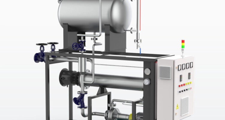
thermal oil heater flame monitoring
For industrial thermal oil heater systems, effective flame monitoring is the critical safety and operational checkpoint that separates reliable, continuous heat delivery from dangerous, uncontrolled combustion events. Unlike other heating systems, a thermal oil heater relies on consistent, clean flame to transfer energy into the heat transfer fluid without causing localized overheating or unburned fuel buildup. A properly designed and maintained flame monitoring system does more than just confirm the burner is on—it ensures every ignition attempt is safe, every flame during operation is stable, and every shutdown happens in a controlled sequence that prevents hazardous conditions from developing inside the combustion chamber.
Real-Time Flame Detection and Verification Methods
Modern thermal oil heater burners use one or more dedicated technologies to confirm the presence and quality of the flame throughout the entire firing cycle. The most common method is a flame rod or flame rectification sensor, which uses the flame itself as an electrical conductor to complete a small DC circuit. When the sensor is clean and properly positioned within the flame envelope, it sends a consistent microamp signal back to the control board to verify combustion is active. If the signal drops below a set threshold, the control system interprets this as a flame failure and immediately shuts off fuel supply to prevent unburned fuel from accumulating in the chamber.
For larger systems or those with more complex combustion patterns, an ultraviolet (UV) or infrared (IR) flame scanner provides a more robust detection option. These optical scanners are mounted to view the flame through a sight tube and react to the specific light spectrum produced by combustion. They are less susceptible to false signals from hot refractory or glowing carbon deposits than simpler sensors. Regardless of the technology, the key is regular verification that the sensor has a clear, unobstructed view of the flame root—the initial ignition zone—and that its signal remains strong and stable even when the burner modulates between low and high fire. Any degradation in signal strength often indicates soot buildup on the lens or a slight misalignment that needs correction before it causes a nuisance shutdown.
Integration with Burner Management and Safety Interlocks
A flame monitoring system does not operate in isolation; it is the central input for the burner management system (BMS) that controls the entire ignition sequence and runtime safety. During startup, the BMS initiates a prepurge cycle to clear any residual gases from the combustion chamber, then energizes the ignition transformer and opens the fuel valve. The flame monitor must detect a stable flame within a very short trial-for-ignition period—typically 5 to 10 seconds. If no flame is verified within this window, the BMS immediately locks out, requiring a manual reset to prevent repeated, unsafe ignition attempts.
During normal operation, the flame monitor continuously watches for any sudden loss of flame. If the flame extinguishes unexpectedly while the fuel valve remains open, the monitor signals the BMS to initiate an immediate safety shutdown, closing the fuel valve and stopping the burner. This system is also interlocked with other critical safety devices, such as the thermal oil flow switch and the high-temperature limit controller. If low flow or an over-temperature condition is detected, the BMS can command a shutdown that is confirmed by the flame monitor, ensuring all safety responses are executed in the correct sequence. This layered approach ensures that a single component failure does not compromise the entire safety chain.
Routine Testing, Calibration and Fault Response Procedures
To maintain reliability, the flame monitoring system requires scheduled verification that goes beyond a simple visual check. A routine test involves simulating a flame failure during a controlled shutdown to confirm the sensor signals loss of flame and the BMS executes the correct shutdown sequence. For optical scanners, this may include using a dedicated test lamp to verify the sensor responds to the correct light frequency. For flame rods, checking the electrical resistance and cleaning the rod to remove any insulating carbon deposits is essential.
Operators should also monitor the flame signal strength displayed on the control panel during different firing rates. A signal that fluctuates wildly or trends downward over time often indicates an emerging problem, such as deteriorating electrode insulation, a dirty scanner lens, or changing combustion conditions. Keeping a log of these signal readings helps identify slow degradation before it causes a failure. When a flame failure alarm occurs, the response procedure should include checking not just the monitor itself, but also all contributing factors: fuel pressure, combustion air settings, ignition spark quality, and the condition of the burner nozzle. This holistic troubleshooting approach addresses the root cause, rather than just resetting the alarm, which prevents the same issue from recurring and extends the safe operational life of the entire thermal oil heater.
Related Posts