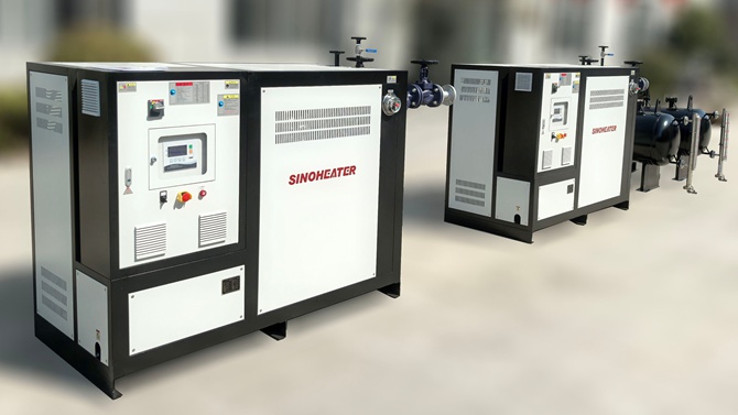
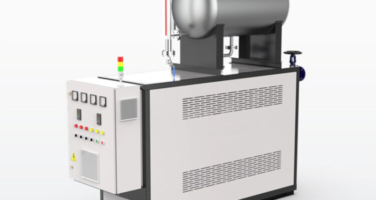
Asphalt plant operations rely on consistent, reliable high-temperature heat to keep aggregate drying, bitumen storage,…
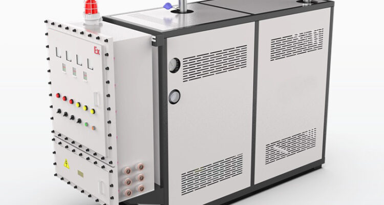
thermal oil heater fuel supply system
A properly maintained fuel supply system forms the backbone of stable, efficient, and safe operation for any thermal oil heater installation. Even minor inconsistencies in fuel delivery can cascade into unstable combustion, unexpected system shutdowns, or avoidable safety risks that disrupt continuous industrial heating processes.
Pre-Combustion Fuel Conditioning and Stability
Before fuel reaches the combustion zone, it must pass through a complete conditioning sequence to ensure consistent physical properties across all operating loads. For heavier fuel types, temperature regulation is critical to maintain the exact viscosity range required for proper atomization, preventing incomplete combustion that leaves unburned deposits on heat transfer surfaces. Continuous filtration removes solid contaminants that could block small orifices, cause uneven spray patterns, or accelerate internal wear on precision fuel delivery components. A steady recirculation loop keeps fuel moving through the supply lines even during low demand periods, eliminating cold pockets and ensuring uniform temperature across the entire system. This conditioning step eliminates most of the common upstream issues that cause unstable flame behavior and fluctuating heater output.
Pressure Regulation and Flow Distribution Logic
Precise pressure control across the fuel supply loop ensures the combustion zone receives a consistent, predictable fuel flow rate under all operating conditions. The pressure regulation point should be positioned close enough to the combustion interface to compensate for minor pressure variations caused by line length, temperature changes, or temporary shifts in system demand. All active fuel supply paths must be arranged to avoid dead legs where stagnant fuel could degrade over extended idle periods, and isolation valves should be placed at logical intervals to support safe component servicing without draining the entire system. Return flow lines must maintain sufficient back pressure to prevent siphoning, ensuring no unexpected flow imbalance develops between the supply and return sides during rapid load changes. This carefully balanced pressure and flow setup prevents sudden flameout events or uncontrolled spikes in heat output that could push thermal oil temperatures beyond safe operational limits.
Leak Prevention and Post-Shutdown Purge Sequence
The fuel supply system must incorporate layered leak protection measures that remain effective both during active operation and after the heater has been shut down. All connection points, seals, and flexible couplings should be routed and positioned to make routine visual inspection easy, so small leaks can be identified and addressed before they develop into larger hazards. Automatic interlocks should stop fuel delivery immediately if unexpected pressure loss is detected, preventing unburned fuel from accumulating inside the combustion chamber. After each operating cycle completes, a timed purge sequence clears residual fuel from the delivery lines and nozzle assembly, eliminating the risk of fuel residue carbonizing, blocking critical orifices, or creating uncontrolled ignition risks during the next startup. This structured protection and purging routine significantly reduces long-term component degradation and minimizes the chance of unplanned safety incidents.
Teams that follow these design and maintenance principles consistently achieve far more reliable heater performance, with fewer unexpected interruptions caused by fuel supply related issues.
Related Posts