Accurately calculating the required heating capacity for a thermal oil heater is a foundational step…
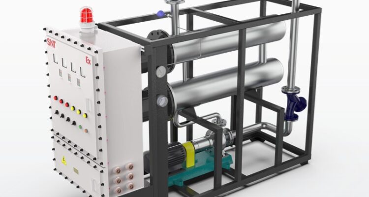
thermal oil heater pipe stress analysis
For teams operating or designing industrial thermal oil heater systems, pipe stress analysis is not just a mandatory engineering check—it is the step that prevents unexpected leaks, cracked welds, and premature failure that can shut down production for days. Unlike steam or water heating loops, thermal oil systems run at high continuous temperatures with far lower operating pressure, which means most failure risks do not come from internal pressure alone. They come from unmanaged thermal expansion, uneven heat distribution, and unintended forces pulling on connected equipment no one accounted for during initial layout. Proper stress work catches these hidden issues before the first startup, and it keeps the full piping loop running safely for decades of continuous operation.
Static Stress Validation for Long-Term Load Safety
The core of any solid pipe stress analysis for thermal oil heater systems starts with mapping all sustained loads that act on the piping 24/7 through normal operation. This includes the weight of the hot fluid flowing through the lines, the mass of the pipe itself, the insulation wrapped around every segment, and all attached components like valves, flanges, and inline filters. Engineers calculate the primary stress generated by these constant loads to make sure it never pushes past the material’s allowable limit, which prevents sudden, catastrophic plastic deformation that can split a pipe open without warning.
This step also accounts for the thermal expansion that happens when the entire loop heats up from ambient temperature to the system’s maximum operating point. When long straight pipe runs heat up, they expand in length, and if that movement is blocked by rigid anchors or poorly placed supports, the resulting secondary stress builds up slowly over repeated heat cycles. Over months of regular start and stop routines, this repeated stress can create fatigue cracks at welds, bends, and flange connections that leak hot fluid without any early visible warning. The analysis maps every point of movement across the full layout, and adjusts support positions to make sure the piping can flex freely without building up dangerous, unplanned stress concentrations.
Force and Moment Check for Connected Equipment
One of the most commonly overlooked parts of thermal oil heater pipe stress work is verifying that the piping never applies excessive, unbalanced force to the nozzles of connected equipment. This includes the main thermal oil heater inlet and outlet nozzles, the suction and discharge ports of the main circulation pump, and the connection points for all downstream heat exchangers. Even if the piping itself is strong enough to hold high stress, too much pull or push on these equipment nozzles can warp sealing surfaces, break internal components, or create gaps that leak hot fluid under pressure.
The analysis calculates the exact thrust and torque that the expanding piping will apply to every single connected nozzle across all operating conditions. For the circulation pump, which relies on precise alignment to avoid vibration and seal failure, keeping these forces well below the equipment manufacturer’s stated limits extends the service life of mechanical seals, bearings, and impellers by years. For the thermal oil heater, balanced nozzle loads prevent unnecessary stress on the heater’s internal coil connections, which stops small internal leaks that can let hot fluid seep into the heater’s insulation and create hidden fire risks. This step also checks every flange connection across the loop to make sure uneven stress does not pull the sealing faces apart enough to create a leak path during normal operation.
Dynamic Stress Assessment for Unplanned Operating Events
A full, thorough pipe stress analysis for thermal oil systems does not stop at static load checks. It also evaluates how the piping will react to unexpected dynamic events that happen over the system’s long service life. This includes sudden pressure spikes from quick valve closures, the temporary force from a safety relief valve popping open, and the vibration that comes from fluid flowing at high velocity through long pipe runs. For systems that sit in regions with high seismic activity, the analysis also accounts for the temporary movement and stress that comes from earthquake events, to make sure the piping does not collapse or pull free from supports during a rare high-magnitude event.
For thermal oil heater systems that run with frequent temperature swings or batch process cycles, the analysis also calculates the system’s natural frequency to make sure it does not line up with the vibration frequency of the circulation pump or any other rotating equipment. If these two frequencies match, even a small amount of initial vibration will amplify over time, shaking piping loose from supports, cracking welds, and wearing out connected components far faster than expected. This dynamic check also maps out all high-vibration zones, so teams can add properly reinforced supports in those areas to dampen movement, instead of letting unaddressed vibration create hidden failure points that no one notices until it is too late.
Related Posts