Accurately calculating the required heating capacity for a thermal oil heater is a foundational step…
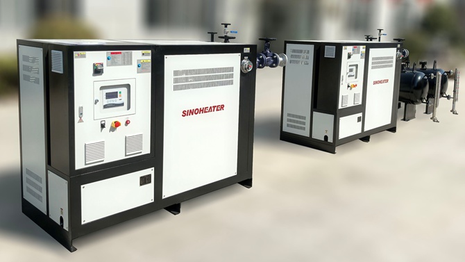
thermal oil heater piping layout
Thermal Oil Heater Piping Layout: A Complete Design Guide
Getting the piping layout right for a thermal oil heater system is not something you can wing. One wrong turn, one missed expansion loop, and you are looking at leaks, pressure spikes, or worse — a fire hazard in a facility that runs hot oil at 300°C and above. This guide walks through the critical decisions that separate a safe, efficient layout from a liability.
Why Piping Layout Matters More Than You Think
Thermal oil systems operate under a deceptively dangerous combination: high temperatures with relatively low pressures. That sounds manageable until you remember the oil expands roughly 8–10% per 100°C rise. Without proper layout planning, that expansion has nowhere to go — and it will find the weakest point in your system.
The piping must handle thermal growth, support dead weight, resist accidental damage, and keep oil contained if something fails. Every decision — from pipe material to valve placement — cascades into safety and maintenance costs down the road.
According to ANSI B31 and NFPA 30, hot oil piping must be constructed as a welded system. Threaded connections are not permitted on oil-carrying lines. This alone eliminates a huge chunk of cheap shortcuts that some installers still try to pull.
Core Principles for Hot Oil Piping Design
Pipe Material and Joint Selection
Seamless carbon steel pipe is the standard for virtually all thermal oil service. Socket weld and butt weld joints are the norm for sizes 1″ through 16″. Once you hit 2″ and larger, flanged connections become practical — and preferred, because they allow disassembly for inspection.
For flanged joints, use spiral wound gaskets on sizes 3″ to 20″, and step up to larger spiral wound or other high-performance gaskets for 22″ and above. Raised face flanges with high-strength studs and nuts are standard practice. Forged steel valves — not cast — should be used throughout.
Brass, bronze, aluminum, and cast iron components are explicitly not recommended. They degrade fast under thermal oil and create failure points you do not want.
Routing and Accessibility
Pipework carrying heat transfer oil should always be laid so it is visible and accessible. Running pipes in ducts, pits, or underground is a hard no. If inspectors or operators cannot see the pipe, they cannot spot a leak before it becomes a problem.
When piping runs from the heater room through other building sections, it will inevitably penetrate fire walls. The fire rating of those penetrations must match or exceed the required fire resistance of the wall. This is not optional — it is a building code and insurance requirement.
Sufficient piping supports are mandatory. Thermal expansion upon heating is significant, and if you do not account for it, you will see buckling, joint failure, or equipment misalignment. Expansion loops, offset legs, and properly anchored supports are how you handle this.
Elevation and Drainage Strategy
High point vents and low point drains are non-negotiable. Every high point in the system needs a vent valve to release trapped vapor during startup and operation. Every low point needs a drain connection to empty the system for maintenance.
Drain and vent connections must be provided with no thread seals — threaded seals on these connections are not allowed. Use proper drain valves and keep them accessible.
The expansion tank placement drives much of the elevation strategy. It should be mounted at the highest point in the closed-loop system — ideally at least 5 feet above the highest piping point, though some engineers accept lower placement with careful review. The tank must sit above the system so vapor naturally rises into it. If the tank is not the highest point, you need high point vent valves throughout and a deliberate burping procedure during commissioning.
A double leg drop or heat-up line arrangement connecting to the expansion tank can force circulation through the tank during commissioning. This helps drive out vapor and air, which is critical because trapped gas causes pump cavitation and hot spots.
Expansion Tank and System Integration
The expansion tank is the heart of the system’s ability to handle thermal growth. It must be top-mounted or remotely mounted at the highest point, ensuring proper venting and eliminating air lock during fill and operation.
The pipe connecting the expansion tank to the system must have no restrictions — no check valves, no isolation valves, nothing that could separate the heater from the vented tank. If that pipe gets blocked or isolated, pressure can build unchecked, and you have a serious safety event.
A minimum liquid level must be maintained in the expansion tank to prevent pump cavitation. A liquid level switch interlocked with the pump and burner should shut everything down if the level drops too low. The switch must be satisfied before the pump can even start.
For systems where the tank contents are exposed to air at elevated temperature, consider a thermal buffer — a vessel that cools the oil before it enters an atmospheric expansion tank. This minimizes oxidation, which is the silent killer of thermal oil systems. Oil oxidizes rapidly above 60°C when exposed to air, forming sludge and acid that eat through equipment from the inside.
Pressure Testing and Commissioning
Never use water for pressure testing a thermal oil system. Any water left inside will flash to steam at operating temperature and cause catastrophic damage. Use nitrogen or dry compressed air instead. Pneumatic testing is the industry standard for good reason.
Before startup, the system must be deaerated. The double leg drop or heat-up line methods mentioned earlier are the primary tools for this. If the expansion tank is the highest point, vapor removal is relatively easy. If not, you must vent every high point manually and repeatedly until no more vapor appears.
After any shutdown — normal or emergency — the circulating pump must keep running for at least 15 minutes (or longer if the manufacturer specifies). This prevents localized overheating and oil degradation in stagnant zones.
Insulation and Leak Detection
Use non-wicking cellular glass insulation on all heated piping and the heater chamber. This is not a suggestion. Oil-soaked fiberglass or mineral wool insulation can spontaneously combust. Cellular glass does not absorb oil, eliminates that fire risk, and meets insurance requirements.
Jacket the insulation with aluminum or liquid-proof mastic. Flanged joints, valves, and pumps should generally be left uninsulated so that leaks are immediately visible. These areas should carry warning labels for contact precautions.
Raised edges or drip trays should be installed beneath pumps, valves, and filters — anywhere leakage is likely. These collect spills and direct them to a sludge tank. Empty them regularly.
Electrical and Safety Clearances
Unprotected electrical cables must not run close to hot oil piping or joints. The fire risk is real. Cable and conduit joints near the system must prevent ingress of thermal oil. Electrical services should never run adjacent to circulating pumps.
All equipment, pipework, and fixtures must be adequately grounded — either directly or through cross bonding per IGEM/UP/16. The heater, pumps, and valve actuators all need proper earthing.
Safety valves must be the totally enclosed type with no lifting lever. Their discharge piping should connect to a closed vented storage tank, not vented to atmosphere.
Every component in the loop — pipe, valves, filters, flanges — must be rated for the system’s maximum temperature and pressure. If it is not rated, it does not belong in the line.
A well-designed thermal oil piping layout is not about following a checklist. It is about understanding that every pipe run, every joint, every support is a decision that affects safety, efficiency, and uptime for years. Get the layout right from the start, and the system runs quietly. Get it wrong, and you pay for it — in downtime, in repairs, or in something far worse.
Related Posts